Week 5: Usability & Housing

Now I have looked a little deeper into what I am building I am going to start wrapping up ose ends as mch as possible as we have 1 week untill we show off our work to our peers and public.
The main loose ends I need to tie up are as follows:
- Building separate databases for usability, proof of concept and demonstration of design.
- 1 x Static product database representing the back-end of a point-of-sale (POS).
- 1 x Database to send the amount to be charged, to represent the front-end of the POS.
- Designing and 3D printing my housing to encapsulate my idea into a somewhat working prototype.
- Re-working my technical package to fit into a small housing for use.
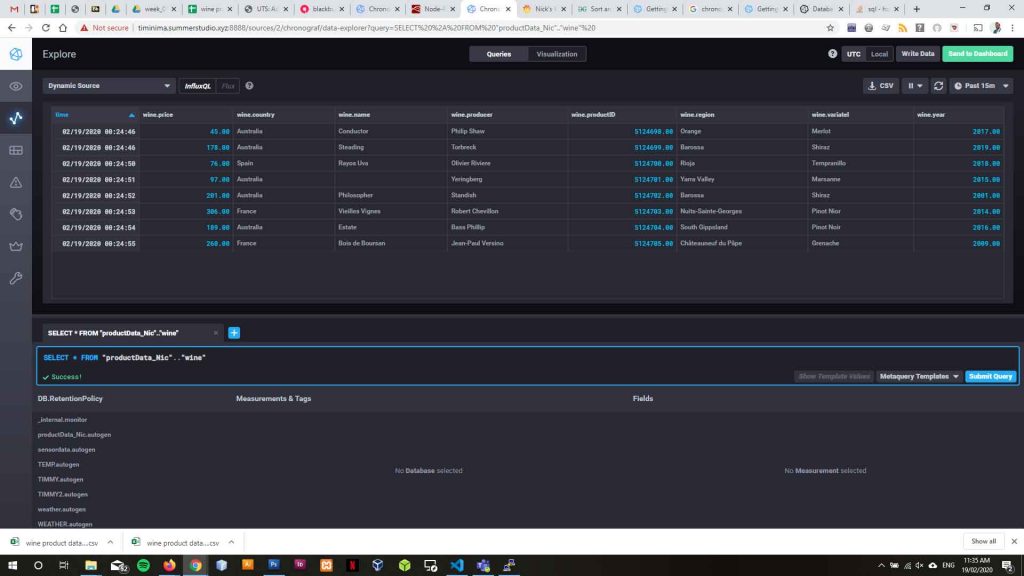
I have built a static database in InfluxDB (productData_Nic) with product information for the products my acquisition device will monitor. To do this I built a small database in Google Sheets and joined the product information followed by copying that information into an inject node in NodeRed and sending that to my product information database.
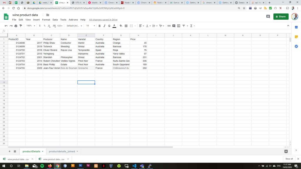
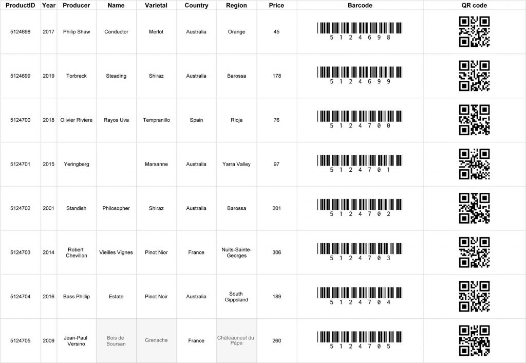
I now need to pull my product pricing data from productData_Nic for the product that is being weighed. To identify each different bottle being weighed I will use barcodes and QR codes. I will scan the code on the product with my mobile device, send that code to my acquisition device which will look up that code in my productData_Nic database and return the price of the product that matches that code.
My acquisition device will store the pricing data and barcode attached to the pricing data and calculate the price in millilitres, within a tolerance level, that should be charged to a customer. The price to be charged will be sent to another database and stored as a record of sale.
msg.query = "SELECT price FROM productData_Nic.autogen.wine WHERE productID = '" + msg.payload + "'";
return msg;
var msg1 = {};
msg1.payload = msg.payload.results[0].series[0].values[0][1];

return msg1;
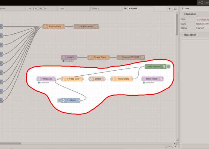
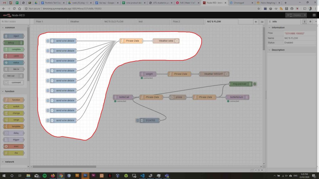
I have successfully sent a scanned barcode to my acquisition device previously. In Node red I have an incoming MQTT node passing the code number to a function which sends a query to my productData_Nic to lookup my product price.
This takes the message payload being the barcode number and inserts it to my query language code.
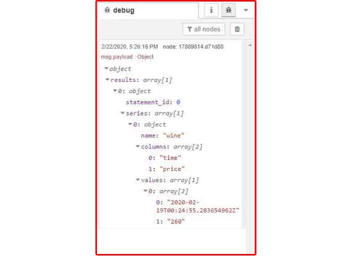
Once the price is found my InfluxDB node returns an object with time and pricing information for the product and when that product was entered into the database.
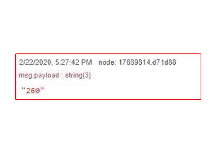
Another function is required to pull that data structure part and publish only the price being returned to the acquisition device for storage.
Requirements
As My acquisition device measures the amount of alcohol missing from a bottle while working in a bar serving customers there are several unique user requirements the housing must meet to ensure the device can acquire correct and consistent data. The requirements are as follows:
- The bottle and the device must stay attached while in use.
- As bars are busy the chances that bartenders will either remember or actively seek to put the bottle that needs weighing back are slim.
- Bottles in bars are not always put back in exactly the same place after use.
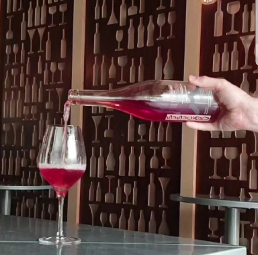
- The housing should have minimal interference with pouring the wine and branding of the bottle being poured.
- Bar staff are trained to pour liquor with the bottles label facing the customer as to continually have the brand in the customers eyesight. For this reason the bottle is typically held by the base as to not cause repetitive strain.
CAD Modeling
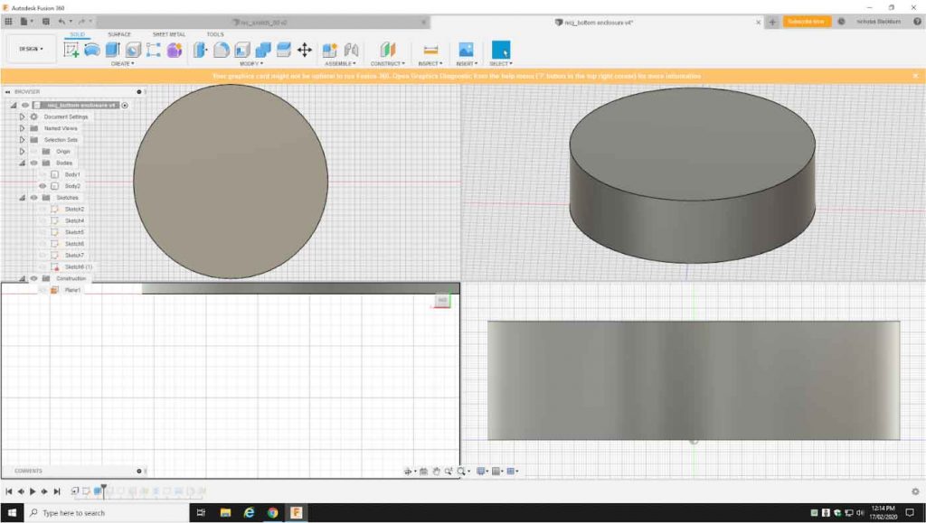
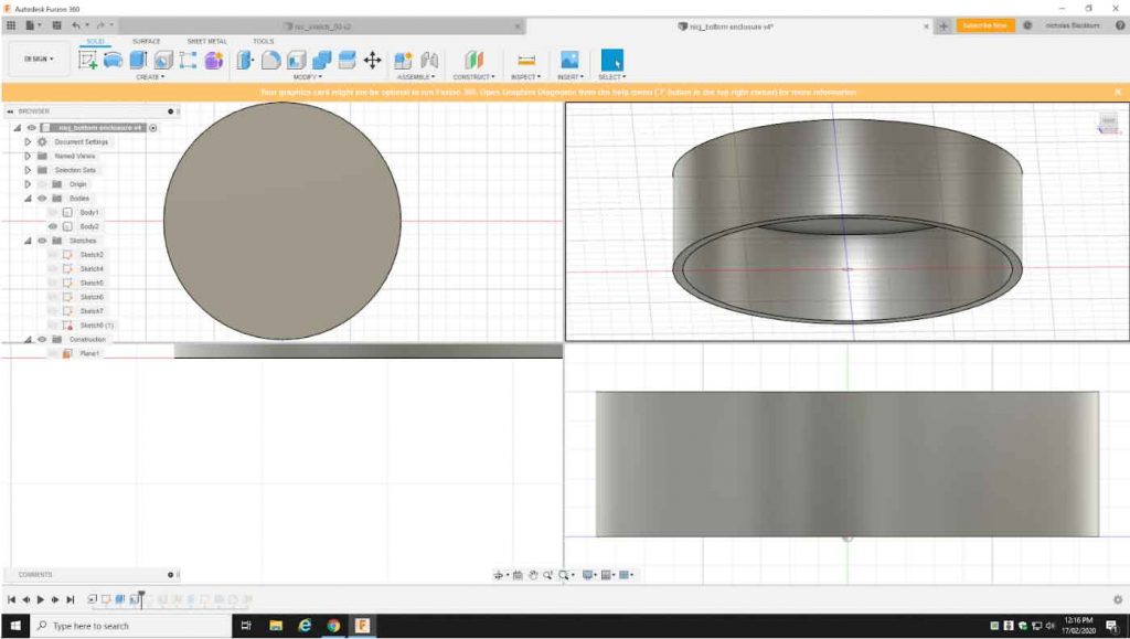
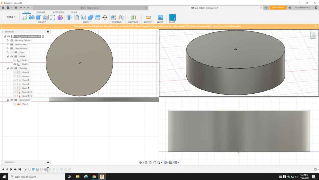
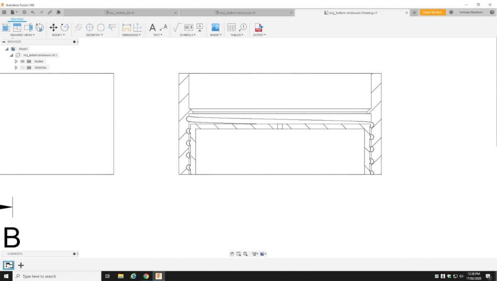
The housing is designed to fit like a sleeve or cup holder for the bottle. With a ring fitted over the neck of the bottle and the ring and the sleeve are held together by string or elastic while in use.
There are four parts to the housing of the technical components:
- The outer sleeve for keeping the bottle in place.
- The weighing plate, where the bottle sits to be weighed.
- The top technical package housing screw in via a regular thread into the outer sleeve. This is where the strain gauge sits under the weighing plate in the strain gauge mount and above the circuitry. Under the strain gauge Mount the HX711 amplifier chip sits, attached to the strain gauge and NodeMCU.
- The bottom technical package housing has a reverse thread to screw into the top housing as to not loosen the top technical housing when tightening. the bottom technical package housing holds all other vital components including a battery. The battery is charged by usb.
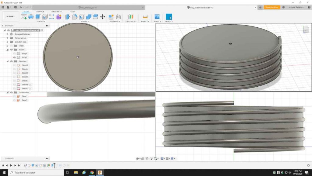
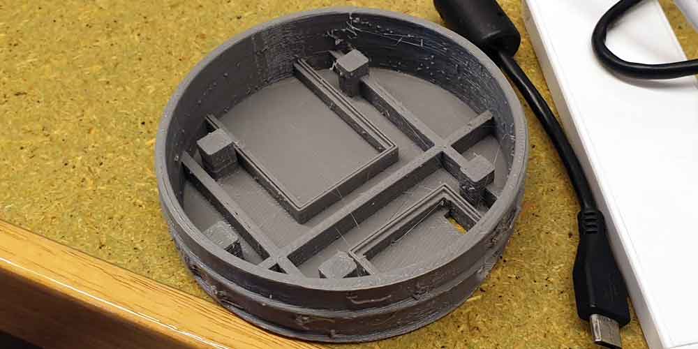
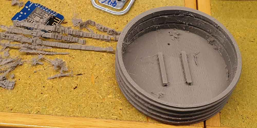
3D Printing
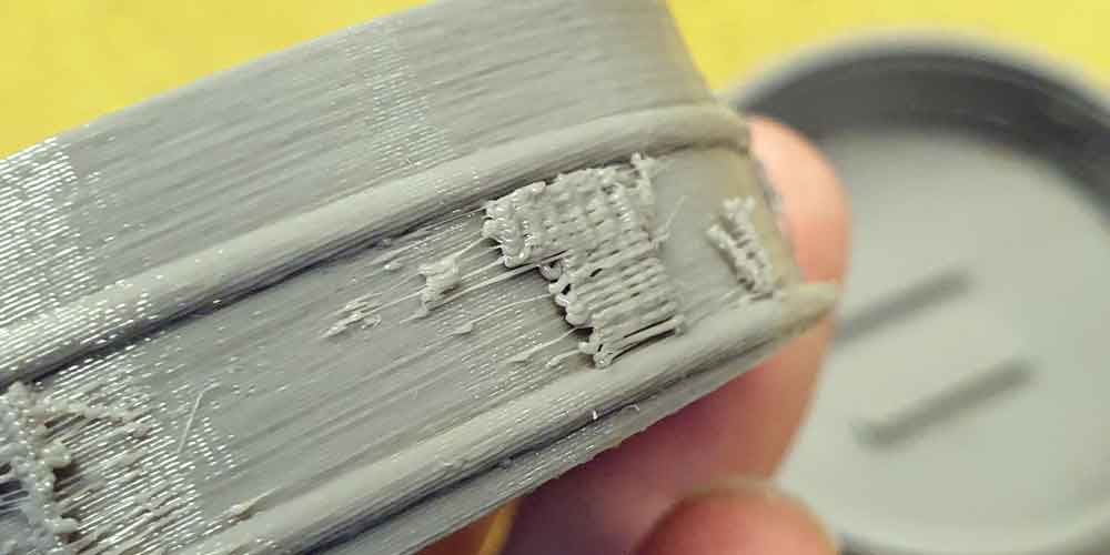
I have 3D printed a sketch model from which I can make adjustments for my final model. The sketch model uses printed support material to print undercuts in the design. This support material can be difficult to deal with especially when threads and mechanical designs are involved. The threads on my sketch model get stuck for this reason.
My final model will be printed with a laser sintered powder that can be easily brushed away. The material is extruded much finer than the sketch model so tolerances with the model should fit easier.
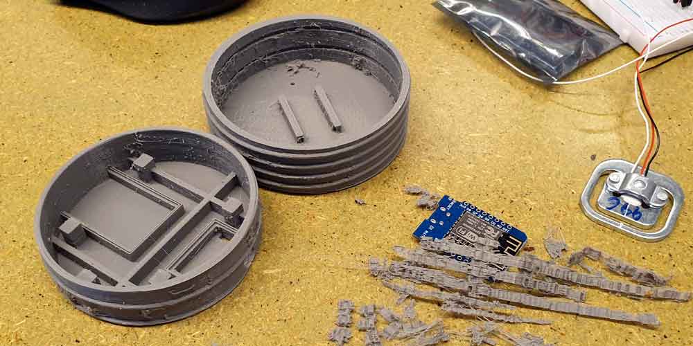
Powering the Acquisition Device
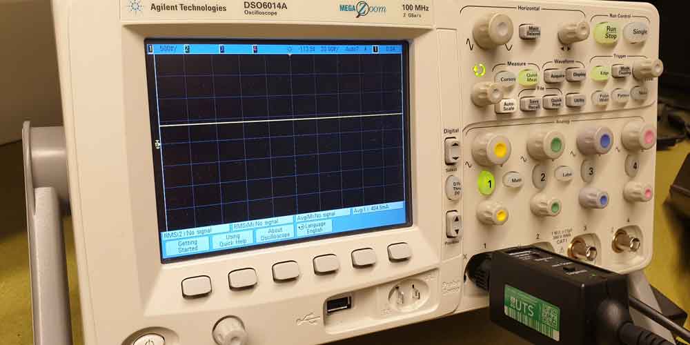
My sketch model outlines what changed needed to be made to make a fit for the final battery housing model.
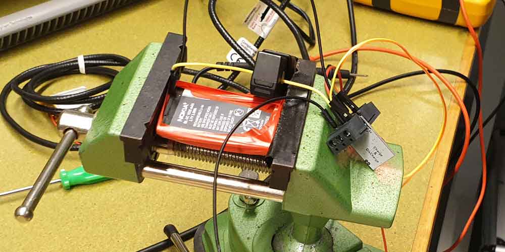
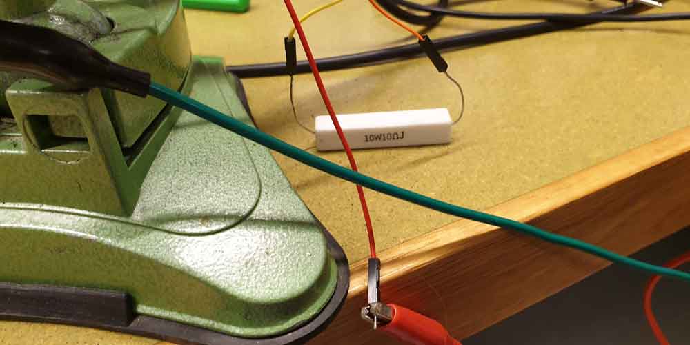
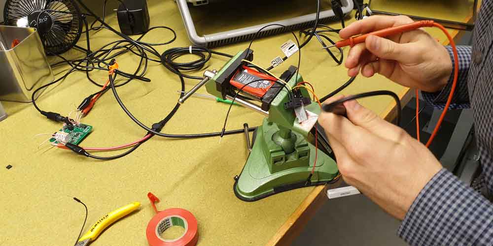
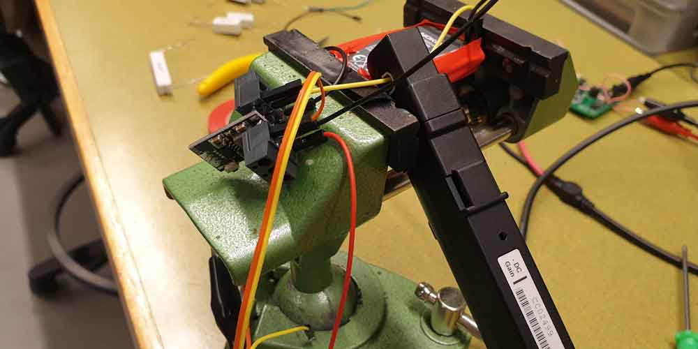
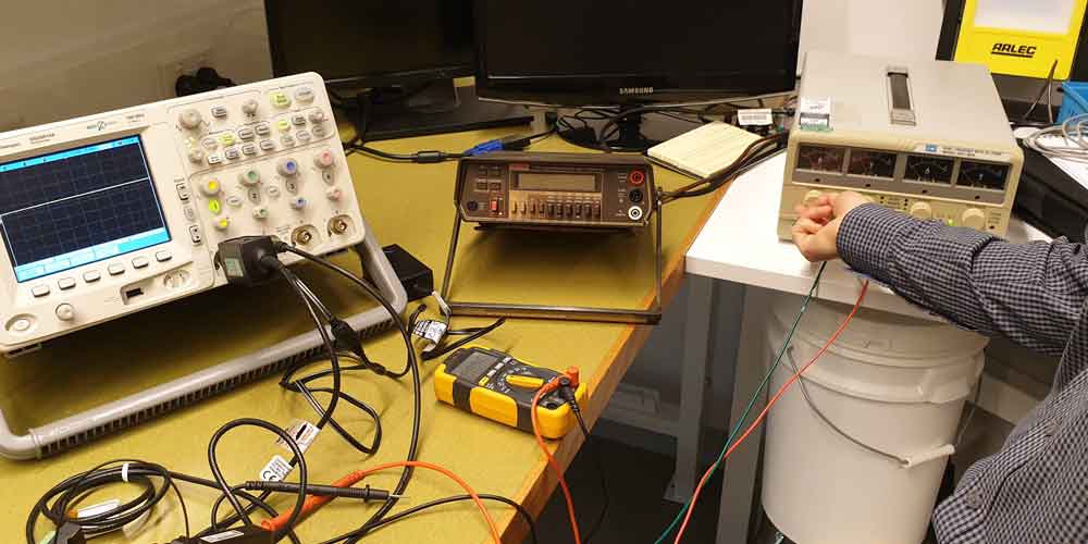
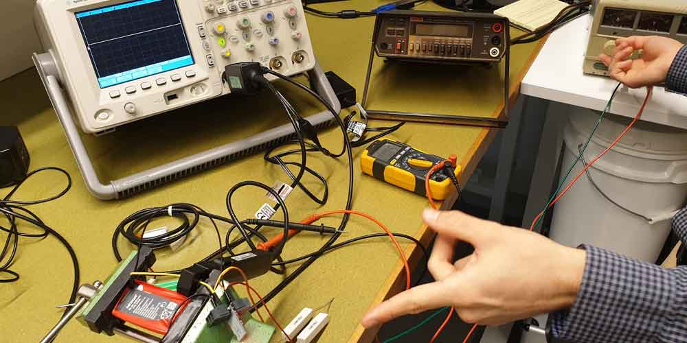
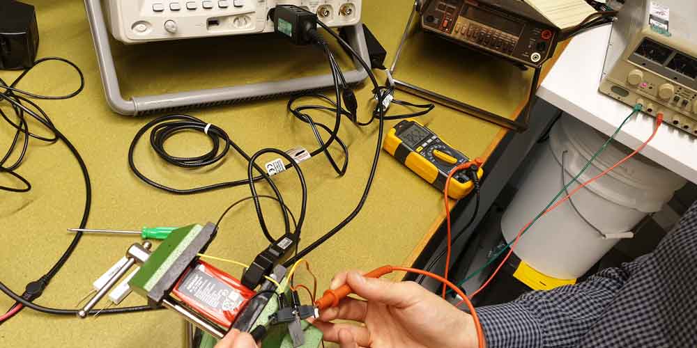
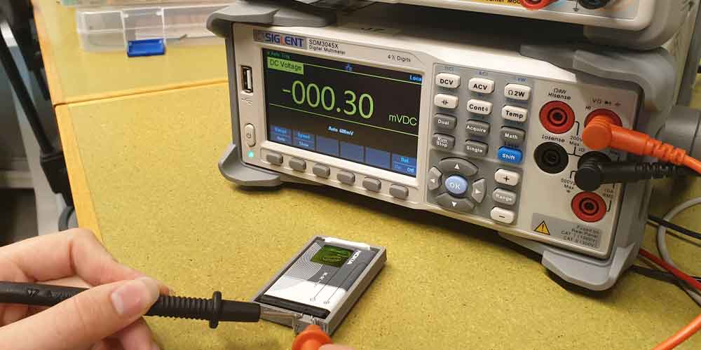
I chose to use a Lithium Ion Nokia battery to power my acquisition device while it is not charging by USB. I needed to determine whether the Nokia Lithium Ion battery had some internal circuitry for charge regulation. If my battery has internal charge regulation I will be able to use my charge module with in built LED indication without building extra circuitry to regulate charge. We had to drain my battery monitoring its recharge when oversupplied power for charging. If the amperage at high supply showed the same current as at amperage at a lower state it would show some regulation of supply is provided by the batteries internal circuit.
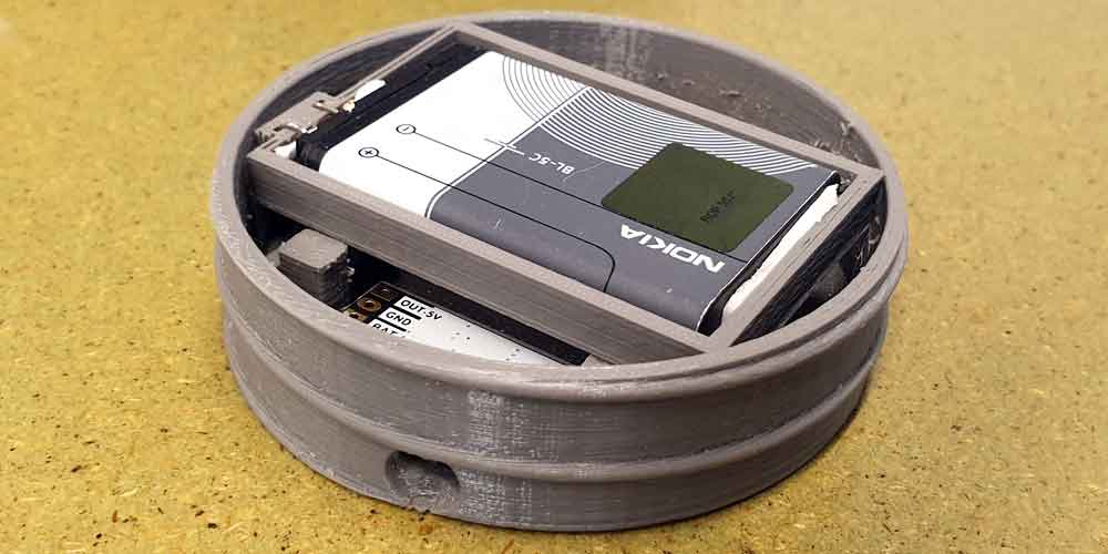
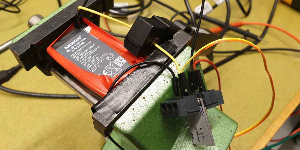
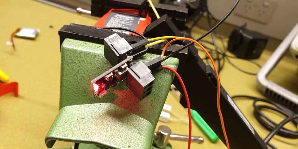
To connect my battery to my internal circuitry I needed to design a housing with nodes connected to the positive and negative terminals. I printed a sketch model first to determine size and fit into the model. I wanted to friction fit my batteries to my terminal and required testing to determine that my friction fit was tight enough to connect to the battery terminals properly.
Charging of the battery will be done externally from the acquisition device as the time left has not allowed to build a micro USB charging input. The Nokia battery has not come with a housing to integrate into my design, as such I have built and 3D printed a housing for my battery to fit into my acquisition device.
I decided I should not solder my final circuit until my final prototype model has returned from being printer from UTS Protospace. This will allow me time to refine my code and resolve any issues with bar codes and price / amount to be charged databases.
Our showcase is next week and we have determined our models should be “showcase ready” by the end of Wednesday’s studio. This will allow our studio to tidy our work areas, set up our displays and partake in the day’s activities. No further development will be undertaken on Thursdays Studio Session.
This tightens my scope of what can be achieved considering I am waiting to solder my compact circuit when I receive my prototype model. My main achievements for next week will include:
- Finalising my bar / QR code scanning and inter database communication.
- Ensuring my prototype fits together mechanically.
- Fitting my internal technical package into the prototype model.
- Soldering my compact circuit and fitting into my model.